The circuit comprises a single 5V controller, two transistors, two light-emitting diodes, five resistors, two capacitors, and a small battery. While a 4-V battery is indicated, 4. 5 V (3 alkaline cells in series) or 3. . In this post I have explained how to construct a simple solar panel regulator controller circuit at home for charging small batteries such as 12V 7AH battery using small solar panel We all know pretty well about solar panels and their functions. The basic functions of these amazing devices is to. . Powered with solar panel, the circuit will give you 5V pure regulated DC voltage. A. . This apparatus is conceived as a straightforward, cost-effective 'comparator', intended for application within a photovoltaic system where a rapid 'too low' or 'perfectly adequate' voltage signal is required. It consists of an oscillator transistor and a regulator transistor. A diode is required between the panel and. .
[PDF Version]
This example shows the design of a boost converter for controlling the power output of a solar photovoltaic (PV) system. In this example, you learn how to: Determine how to arrange the panels in terms of the number of series-connected strings and the number of panels per string to achieve the. . The main components are designed, which consists of three main phases connected in series with each other. It also contains a suitable IGBT electronic key selected. . The post explains how to build a simple 12V solar charger circuit with boost converter capable of charging 12V battery from a 3V solar panel. For this reason the project is introduced as a hobby. We. . Solar Photovoltaic (PV) power generation PROTEUS software. It mainly deals with literature survey.
[PDF Version]
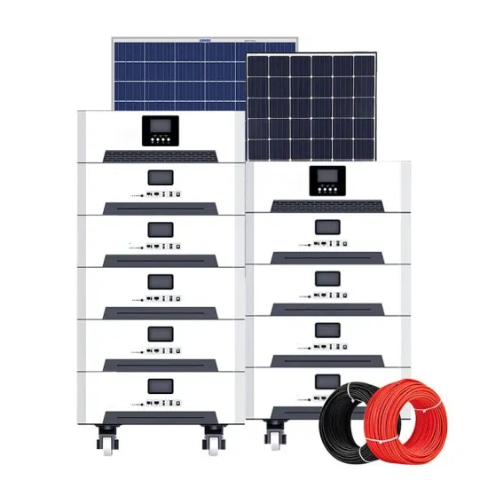
There are 4 main building blocks in a basic solar power system diagram. Here's what they are, and what each of them are for. . Solar power systems vary widely in their power producing capabilities and complexity. Regardless of a given system's capacities and specifications, there's a common thread among most of them: The basic. . In this post, we'll discuss what is solar power plant? It's Diagarm, Layout, Working, and More using illustrations. . So I'm going to use some solar panel diagrams to show you how solar cells work and then describe all of the elements that go up to make a complete home solar system. The diagram above shows the key elements in a solar cell. Solar energy is a sustainable and cost-effective power source.
[PDF Version]
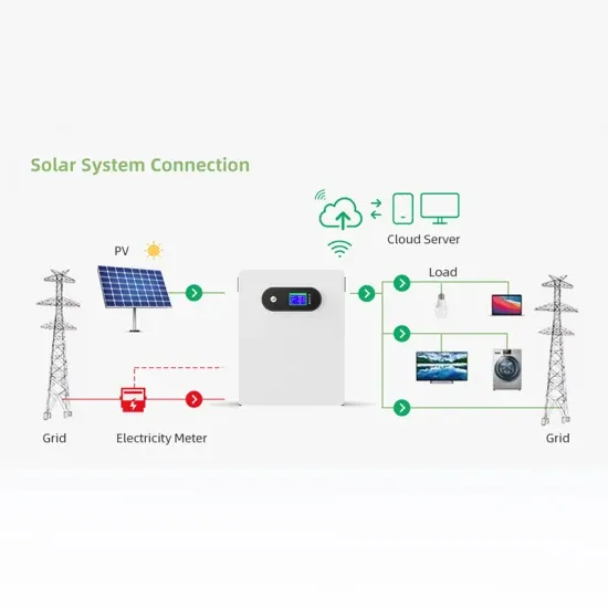
In this guide, we'll walk through how to design your wiring layout, the essential components you'll need, and how to interpret or create diagrams for both grid-tied and off-grid systems. You'll be ready to power up your home or get on the road in no time. What Is a Solar Panel Wiring Diagram? A solar panel wiring. . When it comes to installing a solar power system, a well-crafted solar wiring diagram is essential. Whether you're a DIY enthusiast, professional designer, or seasoned contractor, a clear and detailed wiring diagram can be the difference between a successful project and one bogged down by delays. . A solar panel wiring diagram is the blueprint that makes this possible. A solar array wiring diagram is a visual. . Solar System Wiring Diagram – When it comes to harnessing the power of the sun, understanding the solar system wiring diagram is crucial.
[PDF Version]
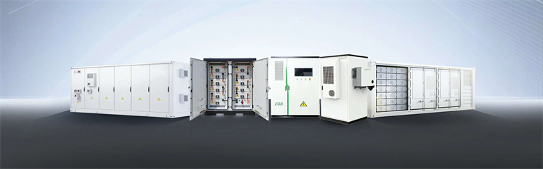
This article examines various types of solar energy storage systems, including battery and grid-tied options. Storage systems turn solar power from a “use it or lose it” resource into a reliable, flexible energy source. We don't need to get into the detail here, but each solar cell contains charged silicon discs that produce electrons. . The AES Lawai Solar Project in Kauai, Hawaii has a 100 megawatt-hour battery energy storage system paired with a solar photovoltaic system. Sometimes two is better than one.
[PDF Version]
Most inverter manufacturers recommend a maximum of 5% voltage drop for the system— typically 2. 5% on either side of the inverter. On large systems, many designers specify an even tighter value of 3% total or less, to maximize the energy harvest. . Disconnect from AC input is a bit more complicated. If grid drops out, there is a momentary overload on inverter as inverter tries to power the collapsed grid, up to possibly the surge current limit of inverter, before it releases AC input pass-through relay. but that doesn't apply if inverters. . Calculating voltage drop in PV circuits is a critical skill for ensuring a solar installation operates at maximum efficiency and safety. For any journeyman electrician or master electrician working with photovoltaics, correctly performing a wire size computation is essential to prevent significant. . PV inverters have a mandated normal operating voltage window, and excessive voltage drops in cabling that effectively moves the nominal operating voltage seen at the terminals of the inverter to one end of this window can result in nuisance tripping of the inverter and an associated loss of. . Use this voltage drop calculator to find the right wire size for your solar electric system. In order to harvest the energy out of the PV panel, a Maximum Power Point Tracking (MPPT) algorithm is required. Voltage drop is used to determine conductor size and length, as well as the spacing between circuit components.
[PDF Version]