The bracket is set up with long and short legs before and after the bracket, and the legs are bolted to the foundation respectively, one end of the diagonal brace is supported at the foot of the long column, and the end of the middle part is a diagonal beam, and the. . The bracket is set up with long and short legs before and after the bracket, and the legs are bolted to the foundation respectively, one end of the diagonal brace is supported at the foot of the long column, and the end of the middle part is a diagonal beam, and the. . Let's face it – most DIY solar enthusiasts get starry-eyed about panels and inverters, then suddenly realize they're holding a photovoltaic bracket structure diagram size table that might as well be ancient hieroglyphics. I once watched a contractor try to install residential racks using. . The MS PowerPoint presentation will provide a comprehensive overview of mountings for solar systems and their components, including MMS and their significance in solar PV systems. The focus will be on the different types of MMS, including fixed, tracker, rooftop, and ground-mounted structures. . a square or rectangular horizontal beam. Includes 1/2” square bend U-bolt sized for specified be and 3/8” column cap assembly hardware. It includes a parts list and installatio instructions for the rack along with acceptable snow loads and wind loads. 4) Ground-mounted photovoltaic panel systems. 1 (I rical portion of solar PV. .
[PDF Version]
ROW TYPE 1 (PURLIN DIAGRAM) SHOW PURLIN POSITIONS DETAIL VIEW A ( 1:4 ) TYP ALL POSNS. ROW TYPE 1 (PURLIN DIAGRAM) SHOW PURLIN POSITIONS DETAIL VIEW A ( 1:4 ) TYP ALL POSNS. evation of the structure and subjected to wind load. The solar panel mounting system's lateral load carrying capacity is often the limiting factor in the mounting system design and the wind forces are often responsib e for generating the lateral loads in c se of solar panel installation. The d 4. . In the intelligent photovoltaic tracker brackets, cold-formed purlins were used to support the photovoltaic panels, and located spannig the horizontal single-axis and the module frame. meet the increasing demand for lightning protection design of PV installations, it is necessary to calculate. . recommended for identifying and tracing utility power lines. Purlin Brackets are prepunched to ma ch standard purlin. There is standard the corrugated roof is 100% watertight.
[PDF Version]

Photovoltaic bracket installation specifications and dimensions table This Design Guide was created to aid in the understanding and optimization of. . Let's face it – most DIY solar enthusiasts get starry-eyed about panels and inverters, then suddenly realize they're holding a photovoltaic bracket structure diagram size table that might as well be ancient hieroglyphics. I once watched a contractor try to install residential racks using. . The brackets form a simple, fast framing system for steel-framed roofs; solar PV modules are mounted in landscape format at either 5° or 15° above the roof sheet, using brackets on a SunLock channel. The channel forms a conduit for cabling. What is a. . Planning and Designing for Rooftop PV: Designers should calculate wind loadson the PV array,specify assemblies and their associated attachments that have sufficient strength to resist the specified loads and specify/detail attachment of the assemblies. Climatic Conditions: Environmental factors such as wind,snow,and seismic activity must be taken into account to ensure the system can. .
[PDF Version]
In the field of photovoltaic power generation, 6063-T6 and 6061-T6 aluminum profiles are commonly used for photovoltaic support bracket. . The Protea Bracket fits most trapezoidal sheet profiles, including pre-ssembled foam core panels (IMPs - Insulated Metal Panels). It has been. . Building a robust foundation bracket for photovoltaic panels is critical for ensuring the longevity and efficiency of solar installations. This guide explores practical methods, material choices, and industry best practices to help installers and DIY enthusiasts create durable mounting systems.
[PDF Version]

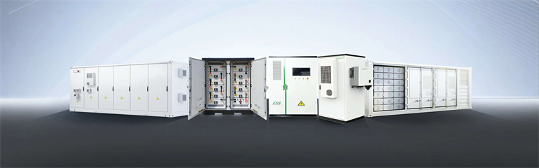
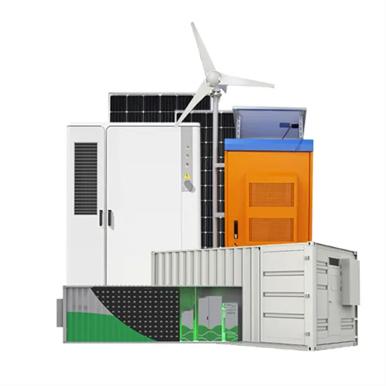
Plans must be legible and drawn to scale in blue or black ink on clear unlined paper. 5" x 11” Maximum Size is 24” X 36”. Plans should be prepared with lettering of sufficient contrast to be readable when scanning. . This manual contains important safety instructions for the Solar Photovoltaic Modules (hereafter referred to as “Modules”) of JA Solar Holdings Co. Installers should follow all safety precautions described in this guide as well as local codes when. . Provide an architectural drawing and riser diagram for the homeowner showing the planned location for future photovoltaic and solar hot water system components. Space requirements and layout for photovoltaic and solar water heating system components should be taken into account early in the design. . Scalable and modular- Solar power products can be deployed in many sizes and configurations and can be installed on a building roof or acres of field; providing wide power-handling capabilities, from microwatts to megawatts. The installation is quick and expanded to any capacity. Photovoltaic modules installed on the ground or on a flat surface occupy, avoiding shading between the rows of modules, an area of approximately 20 mXNUMX/kWp. DWG format available upon request.
[PDF Version]
This guide breaks down how to read a PV system grounding diagram in under 10 minutes. Whether you're reviewing a plan set or prepping for an AHJ inspection, these tips will help you avoid costly mistakes. What Is a PV System Grounding Diagram? A PV system grounding diagram is a dedicated part of. . Grounding (also known as earthing) is the process of physically connecting the metallic and exposed parts of a device to the earth. It is a mandatory practice required by NEC and IEC codes to protect both equipment and personnel from damage and electric shock hazards. This document does not replace any regional, state, provincial, federal or national laws, regulations or standards that apply to the installation, electrical safety. . Abstract—This paper presents basic guidelines on design considerations for large utility-scale photovoltaic (PV) solar power plant (SPP) substation and collector grounding systems for safety aspects. Connect your solar panels to yo r inverter.
[PDF Version]