This operating voltage provides improved electrical efficiency, drives lower aircraft weight, improves aircraft safety/reliability and provides positive environmental impacts. 270VDC is accomplished by rectifying the traditional 3 phase 115VAC 400Hz line-to-line voltages via typical. . These rugged inverters are extremely reliable, designed to provide many years of service in high shock, vibration, humidity, and EMI environments. Combining 3 inverters to form a 3 phase power system is optional. Direct communication, configurable settings, monitoring functions. This inverter allows you to power domestic equipment requiring 120V AC using 12V DC leisure or. . CorePower ® aircraft power conversion systems from Astronics set the industry standard for higher efficiency, cleaner power, and a reduction in total system weight. This MINV-270 will accept a 270Vdc. . The VPTHVM-270 is an Isolated Regulated Bus Converter Module which allows VPT's DV and VPT Series 28V input DC-DC converters to operate from a nominal 270V DC input. A. . For over 40 years we have been providing rugged COTS, MOTS and custom power solutions for designed end-to-end for military and aerospace applications, including avionics, military aircraft, radar arrays, electronic warfare, missiles and missile defense, UAVs, emergency systems, surface ships. .
[PDF Version]
An inverter power source takes input power, filters it to DC, and, using fast solid-state switches, increases its frequency up to 20,000 to 100,000 Hz, and then transforms it into useable welding power with an advanced level of control over the arc. . A simple high voltage generator circuit is explained here which can be used to step up any DC level to about 20 times or depending upon the transformer secondary rating. As can be visualized in the shown high voltage arc generator circuit diagram, it employs a standard transistor blocking. . Summary: Explore how pulse high voltage modules and inverters drive innovation across industries like renewable energy, industrial automation, and electric vehicles. Discover their applications, efficiency benefits, and market trends. This allows the operator to tailor the bead profile, improve arc starting, increase travel speeds, perform better on thinner materials and thinner sections as well as. . source: An Overview Introduction of VSC-HVDC: State-of-art and Potential Applications in Electric Power Systems; Feng Wang, Tuan Le, Anders Mannikoff, Anders Bergman; Cigrè International Symposium, Bologna, Italy, Sept. . planning of the power transmission. In the beginning all HVDC schemes used mercury arc valves, invariably single phase in construction, in contrast to the low voltage polyphase u its used for industrial application.
[PDF Version]
This error indicates that the voltage in the inverter's DC bus, which connects to the solar panels, has exceeded the safe operating limit. . This guide explains how to troubleshoot a "OV-BUS" error on an Autarco inverter. I have a problem where I keep getting intermittent fault 19 (bus voltage too high). I measured the 2 PV inputs and they are 358vdc consistently. This voltage is. . BUS voltage fault: BUS overvoltage or the difference between the positive and negative BUS voltage exceeds. Check the PowerRouter firmware and. .
[PDF Version]
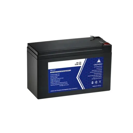
This is caused by low intermediate circuit DC voltage. This can be caused by a missing supply voltage phase from a blown fuse or faulty isolator or contactor or internal rectifier bridge fault or simply low mains voltage. POSSIBLE FIXES: Check mains supply and fuses. . Summary: Understanding why an inverter doesn't generate high voltage is critical for solar energy systems, industrial applications, and residential power solutions. This article explores common technical issues, troubleshooting steps, and innovations like EK SOLAR's adaptive voltage regulation t. . Summary: Is your solar inverter showing high voltage but failing to deliver power? This guide explores common causes, repair strategies, and prevention methods for capacitor-related failures in renewable energy systems. Obviously, the current output is limited by the size of the capacitors and the current carrying capacity of the switches. Typical IC switched capacitor inverters have maximum output. . Now, if I understand things right, an "at rest" nominal 12V battery will show an open circuit voltage of about 12. 10 when discharged to 50%, and about 11. At 10 V, it would be long gone, or at least damaged. Why do these inverters allow the. .
[PDF Version]
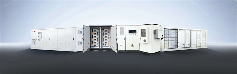
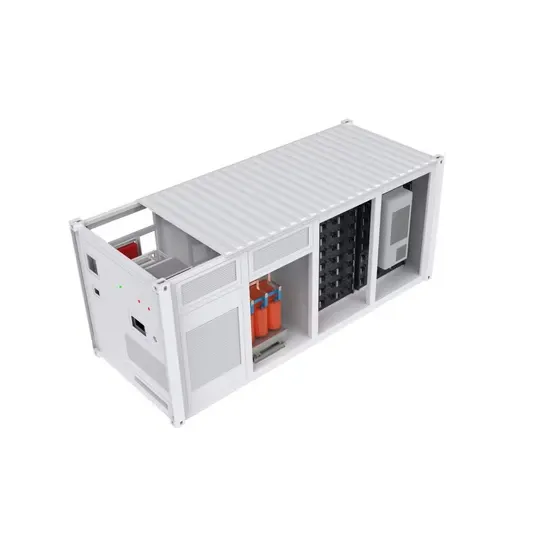
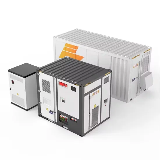
This diagram shows the 3kW~6kW inverter system: DC power from the battery and PV array goes through safety fuses and relays, a DC isolation switch, and capacitors. The inverter then converts DC to AC, which is filtered and stabilized, before outputting clean AC power to the grid and. . Solis S6 11. 4kW Single Phase High Voltage Energy Storage Hybrid Inverter The S6 (Series 6) hybrid energy storage string inverter is the latest in hybrid inverter technology, versatile and flexible for the growing solar storage marketplace. This easily scalable hybrid inverter can be DC-coupled to a variety of batteries post-installation as well as can be paralleled to. . The Livoltek HP1-3~6kW S2 series of single-phase energy storage inverters, with their superior multifunctionality and high-quality performance, bring a qualitative improvement to residential and commercial energy management. Wide battery voltage 85~480V, max. • High MPPT efficiency up to 99.
[PDF Version]
Understanding the inverter voltage is crucial for selecting the right equipment for your power system. These values signify the nominal direct current (DC) input voltage required for the inverter to. . Bonding ties all metallic components together so no dangerous voltage difference exists between racks, frames, or chassis. Peak Efficiency The peak efficiency is the highest efficiency that the inverter can achieve. Read on to learn how to convert AC to DC with our voltage-to-amperage calculator.
[PDF Version]