The new system meets nearly 100% of the campus' Physical Education building's heating needs, and about 50% of its electricity, while also significantly enhancing energy efficiency and driving a reduction in carbon emissions. . Below are current projects related to thermal energy storage. Lead Performer: Oak Ridge National Lab – Oak Ridge, TN. Lead Performer: Oak Ridge National Laboratory – Oak Ridge, TN Lead Performer: Georgia Tech Research. . The California Energy Commission's (CEC) Energy Research and Development Division supports energy research and development programs to spur innovation in energy efficiency, renewable energy and advanced clean generation, energy-related environmental protection, energy transmission, and distribution. . NLR's thermal management research looks to optimize battery performance and extend useful life for various applications, including electric vehicles (EVs). This EV accelerating rate calorimeter is one example of the numerous advanced thermal characterization tools used by NLR researchers. Why Thermal Management Matters in Energy Storage. . Researchers within the Thermal Energy Conversion and Storage Group are involved in a number of projects that are exploring challenges around; clean energy solutions; cold chain technologies; thermal energy storage and thermal management technologies. The increased adoption of heat pumps, alongside the electrification of transportation and other demands, strains the grid's capacity.
[PDF Version]
A thermal energy battery is a physical structure used for the purpose of storing and releasing . Such a thermal battery (a.k.a. TBat) allows energy available at one time to be temporarily stored and then released at another time. The basic principles involved in a thermal battery occur at the atomic level of matter, with being added to or taken from either a solid mass or a liquid volume which causes the substance's to change. Some thermal bat.
[PDF Version]
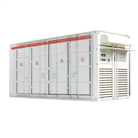
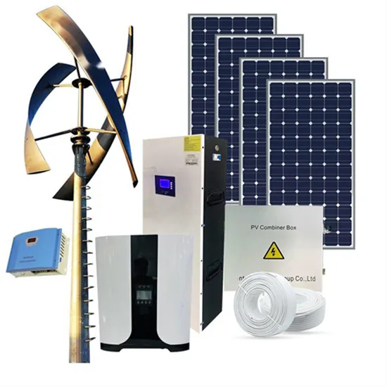
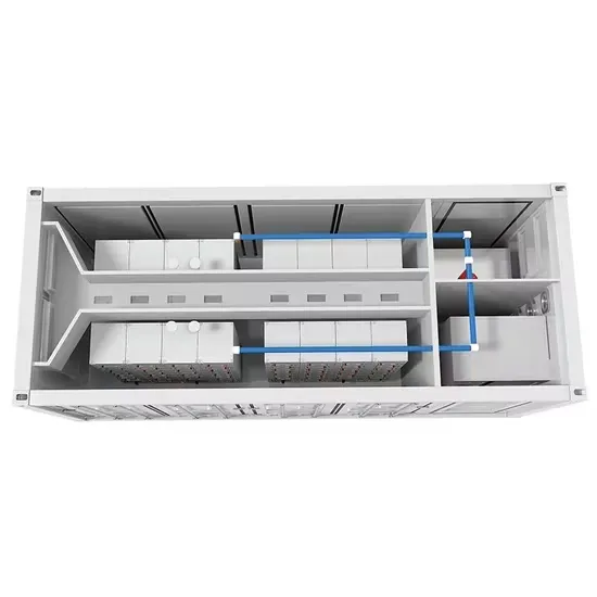
Figure 1 shows the control structure diagram of PV and ESS system, which consists of three main parts: photovoltaic module, energy storage module and control module. . A solar energy storage system diagram is the foundational roadmap for any successful solar power installation. It's more than just a drawing; it is a detailed plan that illustrates how every component connects and interacts to generate, store, and deliver power. For homeowners, installers, and DIY. . Expert insights on photovoltaic energy storage systems, BESS solutions, mobile power containers, EMS management systems, commercial storage, industrial storage, containerized storage, and outdoor power generation for South African and African markets Explore our comprehensive photovoltaic storage. . Internal structure diagram of photovoltaic energy stor e system,and output the generated el irectly converting solar energy throug the photovoltaic effect. The system structure is very flexible. DC-DC converter and solar are connected on common DC bus on the PCS. Find out everything you need to produce these important design elements without encountering any drawbacks Creating the photovoltaic system diagram represents an important phase in. .
[PDF Version]
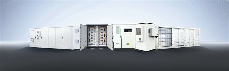
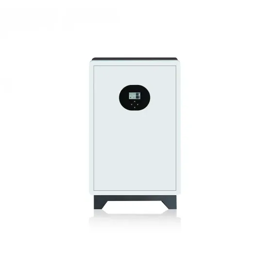
A typical BESS includes four core components: the battery module, battery management system (BMS), power conversion system (PCS), and energy management system (EMS). . Battery Energy Storage Systems, or BESS, help stabilize electrical grids by providing steady power flow despite fluctuations from inconsistent generation of renewable energy sources and other disruptions. Our solution encompasses not just the core technology, but our proven expertise in delivering full turnkey solutions with seamless HV/MV integration capabilities. This ensures a. . Utility-scale battery energy storage systems (BESS) are a foundational technology for modern power grids. Together with you, we design and engineer your customized large scale energy storage system INTILION. . Reflects the average percentage of power available over the previous 12 months, weighted by GWh for projects that have contracted an Availability Guarantee and been in operation for over 30 days.
[PDF Version]
At the heart of this understanding lies the battery energy storage system diagram—a visual roadmap that explains how energy flows, how safety is managed, and how power is converted. Flywheel Energy Storage: Your Childhood Top Went Pro Picture your old spinning top—now make it weigh 10 tons and spin at 40,000 RPM. That's flywheel energy. . Compressed-air-energy storage (CAES) is a way to for later use using. At a scale, energy generated during periods of low demand can be released during periods. The first utility-scale CAES project was in the Huntorf power plant in, and is still operational as of 2024. Various strategies including hybridization, doping, pore structure control, composite formation and surface functionalization for improving the capacitance an ic energy, and release out upon demand. They work by spinning up a heavy disk or rotor to high. .
[PDF Version]
Modernize your building's thermal management with Thermal Energy Storage. Thermal energy storage (TES) is a reliable solution for cost-effective, sustainable heating and cooling. Battery systems have so far dominated the energy storage conversation—but Thermal Energy Storage (TES) systems, often overlooked, are rapidly proving indispensable in strengthening grid. . Thermal energy storage (TES) is a critical enabler for the large-scale deployment of renewable energy and the transition to decarbonized building stock and energy systems by 2050. This is because thermal storage allows for the preservation of energy when it is not needed so that it can be used more. . As of February 2025, twelve states have energy storage targets, the largest of which is New York with a goal of 6,000 MW by 2030. In mid-2024, lawmakers in Rhode Island established a 600 MW energy storage goal to be achieved by 2033. The. . We provide a cost-effective solution for industries such as Chemical & Petrochemical, Food & Beverage, Paper & Printing, and Mining Our Solution can be integrated with renewable energy sources like PV, using excess energy to charge the system and provide a continuous, green heat supply.
[PDF Version]