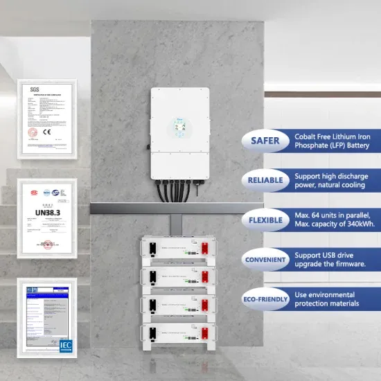
The above graph shows the current-voltage (I-V) characteristics of a typical silicon PV cell operating under normal conditions. The power delivered by a single solar cell or panel is the product of its output current and voltage (I x V). Knowing the electrical I-V characteristics (more importantly P. . Interconnecting several solar cells in series or in parallel merely to form Solar Panels increases the overall voltage and/or current but does not change the shape of the I-V curve. An analog MPPT circuit directly uses these values to find the equivalent operating maximum power point. If voltage is pressure, current (measured in amps) is the flow rate.
[PDF Version]
A solar panel wiring diagram is the blueprint that makes this possible. In this guide, we'll walk through how to design your wiring layout, the essential components you'll need, and how to interpret or create diagrams for both grid-tied and off-grid systems. This diagram will serve as a blueprint for your project, helping you plan the placement of each panel and ensure an efficient and effective installation. The first. . One very important step when constructing your own solar setup is putting together a solar panel wiring diagram (or schematic). Before Installation, take care of any obstructions to sunlight. Whether you're a DIY enthusiast, professional designer, or seasoned contractor, a clear and detailed wiring diagram can be the difference between a successful project and one bogged down by delays. .
[PDF Version]
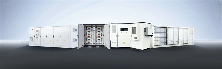
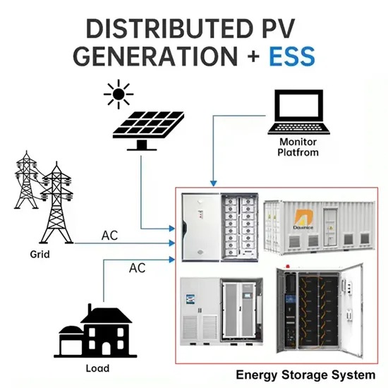
When doing solar PV design or drafting it becomes very imperative to understand the difference between One Line Diagram vs Three line Diagram Let's have a closer look to understand what it means in Solar Drafting Services. When doing solar PV design or drafting it becomes very imperative to understand the difference between One Line Diagram vs Three line Diagram Let's have a closer look to understand what it means in Solar Drafting Services. Therefore, this review paper conducts an in-depth analysis of the accuracy of PV models in reconstructing characteristic curves for different PV panels. The limitations of existing PV models were identified based on simulation results obtained using MATLAB and performance indices. Guidelines for Grid Connected System SizingSolar PV system sizing will be limited by two factors, the amount of. . The Federal Energy Management Program (FEMP) provides this tool to federal agencies seeking to procure solar photovoltaic (PV) systems with a customizable set of technical specifications. Select the plus sign in the rows below for more Solar Panels perform at optimum capacity when placed in direct. . The photovoltaic system diagram is the fundamental design asset for installing an efficient solar energy system. DWG format available upon request.
[PDF Version]
This document provides recommendations for the installation of the Vestfrost Solutions Solar Pole Energy System and identifies some of the hazards associated with the handling and installation. Here we discuss the four-step approach to s arranged for or completed by the PV support structure vendor. 1 m) to more than 25 feet. . Impact driving is a traditional and widely used method in pile installation—where a heavy weight, or hammer, repeatedly strikes the top of the pile—driving it into the ground. However. . Mark post locations in an E/W line according to the predetermined pole spacing diagram array layout plan provided by MT Solar. Ensure spacing is from center of post to center of post. Call today to find out what he n than comparable driven piles or drilled shafts. This manual does not list all precautions needed for safe work. Be sure to follow OSHA guidelines.
[PDF Version]
The figure below shows the schematic diagram of a chilled water system with heat recovery chiller. . ceeding energy code minimum requirements. A comprehensive approach to system design can minimize the power draw of the entire system are inherently easier to control for highest eficiency, lower first costs and lower energy costs. Right-sizing equipment means smaller electrical conne tions—a great. . Thermal Energy Storage (TES) for space cooling, also known as cool storage, chill storage, or cool thermal storage, is a cost saving technique for allowing energy-intensive, electrically driven cooling equipment to be predominantly operated during off-peak hours when electricity rates are lower. The impurities in the cooling water circuit are accumulated, and thus the scales and deposits are built up in the condenser tubes, creating fouling problems on the condenser heat. . entropically as shown by the curve 1-2 on p-v and T-s diagrams. Any Questions? A chiller is a heat transfer device.
[PDF Version]
straightforward wiring diagram and step-by-step guide. Wiring a 12V solar panel typically involves connecting the e installation and maintenance of solar panel systems. These diagrams provide a vi ual representation of how the panels are connec. Summary: Discover professional techniques for welding roof photovoltaic panels, including step-by-step installation methods, industry best practices, and data-backed insights. Learn how proper welding ensures system durability and energy efficiency in solar projects. Instal ation should only be performed by qualified personnel. . Photovoltaic panel rack welding method diagram Photovoltaic panel rack welding method diagram What are the components of a solar stack pedestal system? The system is a non-separately derived system. This guide explores industry best practices, cost-saving strategies, and emerging trends in photovoltaic panel deployment for commercial and residential applications. Mechanical connectors can be mounted to a module or racking frame with lay-in features which accept a copper wi e that bonds and grounds components, said Zwit. case of sale or disposal of the modules. The module is considered to be in. .
[PDF Version]