Battery energy storage system assembly rack diagram
Battery racks can be connected in series or parallel to reach the required voltage and current of the battery energy storage system. These racks are the building blocks to creating a large,high-power
Battery Energy Storage System Diagram: A Complete
In this comprehensive guide, we will dissect the components of a battery energy storage system diagram, explore the differences between AC
Schematic diagram of a typical stationary battery
Schematic diagram of a typical stationary battery energy storage system (BESS). Greyed-out sub-components and applications are beyond the scope of this work.
ENERGY STORAGE CABINET ASSEMBLY DIAGRAM
Solar energy intelligent storage control system s20 An internal lithium battery, a highly efficient solar panel, intelligent adaptive energy control and robust construction come together to provide
Standard and Seismic Battery Racks
The following steps show how to assemble standard and seismic battery racks for flooded lead acid batteries. Also refer to the assembly drawing supplied with the rack shipment for specific details of
Utility-scale battery energy storage system (BESS)
This reference design focuses on an FTM utility-scale battery storage system with a typical storage capacity ranging from around a few megawatt-hours (MWh) to hundreds of MWh.
Battery Control Unit Reference Design for Energy Storage Systems
This design uses a high-performance microcontroller to develop and test applications. These features make this reference design applicable for a central controller of high-capacity battery rack applications.
Battery Energy Storage System Components
Explore the key components of a battery energy storage system and how each part contributes to performance, reliability, and efficiency.
Battery Energy Storage System SLD (Single Line Diagram)
Battery Energy Storage System (BESS) Single Line Diagram is used to explaining DC, PCS, AC protection, SCADA, transformer and also grid interconnection for utility-scale systems.
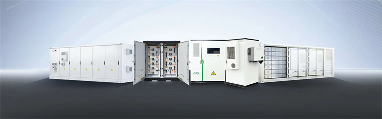
The Key Components of Battery Energy Storage Systems (BESS)
Several modules create a battery rack, and multiple racks are connected to form battery banks or arrays, constituting the battery side of the system. Figure 0 depicts the configuration of a BESS rack.
PDF version includes complete article with source references. Suitable for printing and offline reading.